
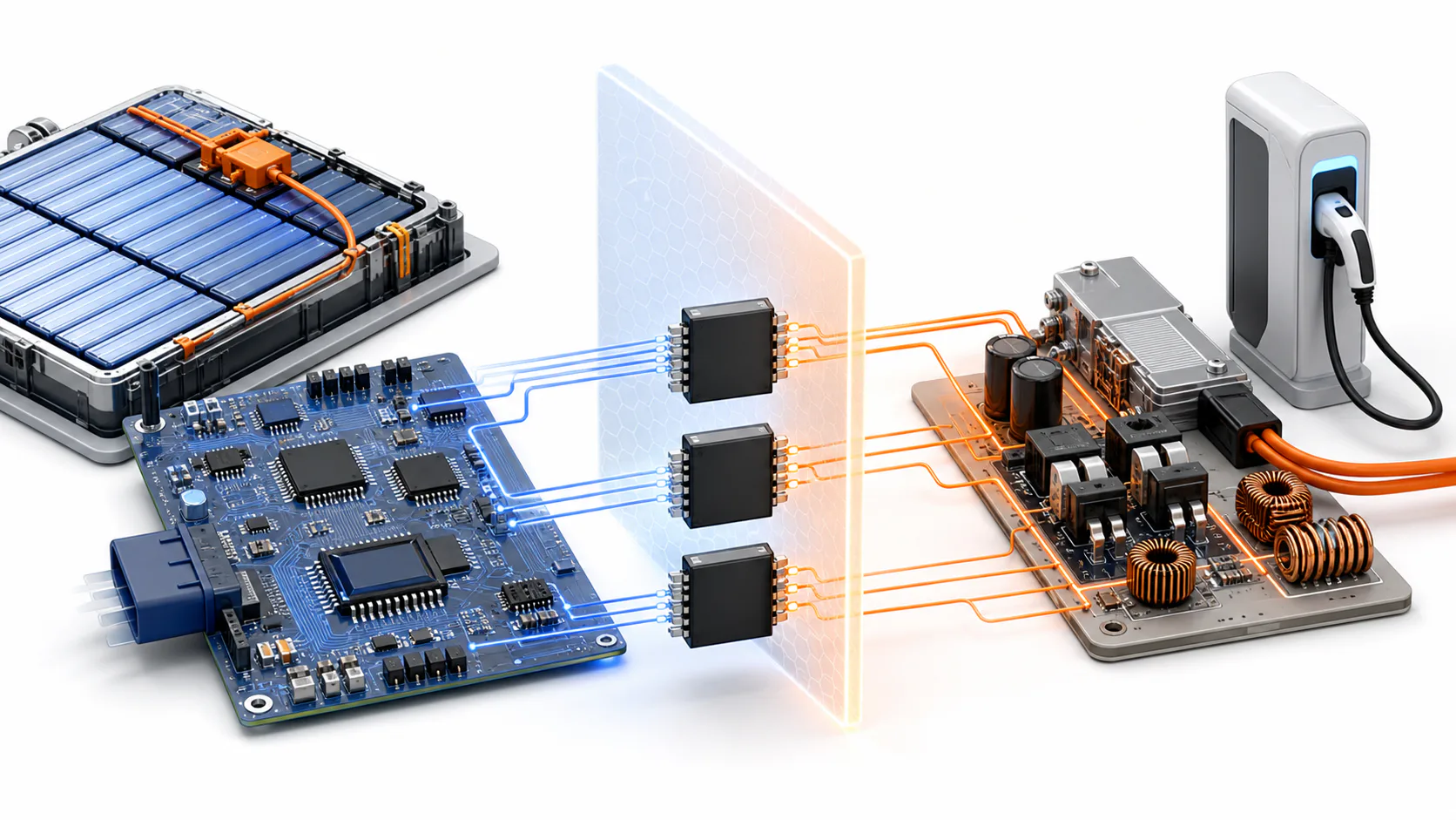
Battery systems, chargers, inverters and industrial drives place low-voltage control beside dangerous voltages and fast switching nodes. Isolation devices allow information or drive signals to cross that boundary without creating an uncontrolled conductive path.
That role makes an isolator more than an interface IC. It is part of the safety, EMC and timing architecture. Procurement teams should resist a pin-compatible comparison until the barrier and application evidence are understood.
Isolation performs several different jobs
Digital isolators move logic, clocks or communication. Isolated amplifiers and converters carry measurement information. Isolated gate drivers command power switches while managing timing and fault response. Isolated power may also be needed on the remote side.
These functions have different specifications. A device suitable for a low-speed status line may be unsuitable for a current-sampling path or SiC gate drive. Start by defining the function, working voltage, transient environment, required lifetime and failure response.
Read the insulation evidence carefully
Data sheets use several voltage terms that are not interchangeable. Repetitive working voltage, transient withstand, surge rating and production test voltage answer different questions. Creepage, clearance, package material group and pollution degree interact with board layout and the applicable equipment standard.
Barrier technology and package construction affect lifetime under continuous electric-field stress. Buyers should request the exact safety certificates and qualification reports for the orderable package. A family-level certification statement is not enough when the alternate package or channel configuration differs.
Fast power stages raise the EMC bar
SiC and fast-switching IGBT stages can produce steep common-mode transients. An isolator must maintain correct output behavior while the reference on the other side moves rapidly.
Compare common-mode transient immunity under the actual supply, temperature and edge conditions. Examine propagation delay, channel-to-channel skew, pulse-width distortion and startup state. In a gate-drive or protection loop, a small timing difference can alter dead time or fault clearing.
Run tests with the final power module, gate resistance, PCB and switching speed. A quiet evaluation setup cannot represent the common-mode environment of an inverter.
Fail-safe behavior belongs in the comparison
Define the output when input power is absent, the barrier input is open or communication stops. Check undervoltage lockout, default state, glitch filtering and recovery after brownout.
For BMS and charging systems, confirm how diagnostic coverage is maintained and how an isolation fault reaches the system controller. Software should not assume that every communication loss has the same cause.
Qualify documentation and support
Suppliers such as Texas Instruments and Analog Devices offer broad isolation portfolios, while additional vendors can provide credible options for specific functions. The sourcing comparison should include safety manuals, models, errata, PCN terms, lot traceability and application support.
Introduce an alternate in gates: document review, bench characterization, system EMC and fault injection, environmental reliability, then controlled production. Preserve waveform and thermal evidence for both sources.
The procurement conclusion
Isolation is where electrical safety, signal integrity and power-stage behavior meet. A replacement that matches pins but changes barrier lifetime, timing or fail-safe behavior can invalidate the surrounding design assumptions.
Buyers should approve the isolated function, package and evidence set together. The objective is not another logo on the AVL; it is a second safety boundary the system can trust.
Safety compliance depends on the complete equipment design and applicable standards. Confirm requirements with qualified engineering and compliance teams.