
Connect a camera to a monitor, see a picture, and give it a quick visual check: no black screen, no obvious corruption, so the unit passes.
But is the camera actually good?
A few pixels may already be defective. A frame timestamp may occasionally jump. A sideband interface may fail intermittently. Other faults appear only at a specific resolution, color format, or frame rate. They do not necessarily produce a black screen; they remain buried in a continuous video stream.
As resolution and frame rate rise, a production test based on a person watching the screen becomes less dependable.
In June 2026, German test-equipment supplier GÖPEL electronic highlighted a modular test solution built around Video Dragon 6222. The unit itself was not a brand-new launch. The update expanded the overall test capability for high-resolution industrial cameras, automotive imaging, and display equipment.
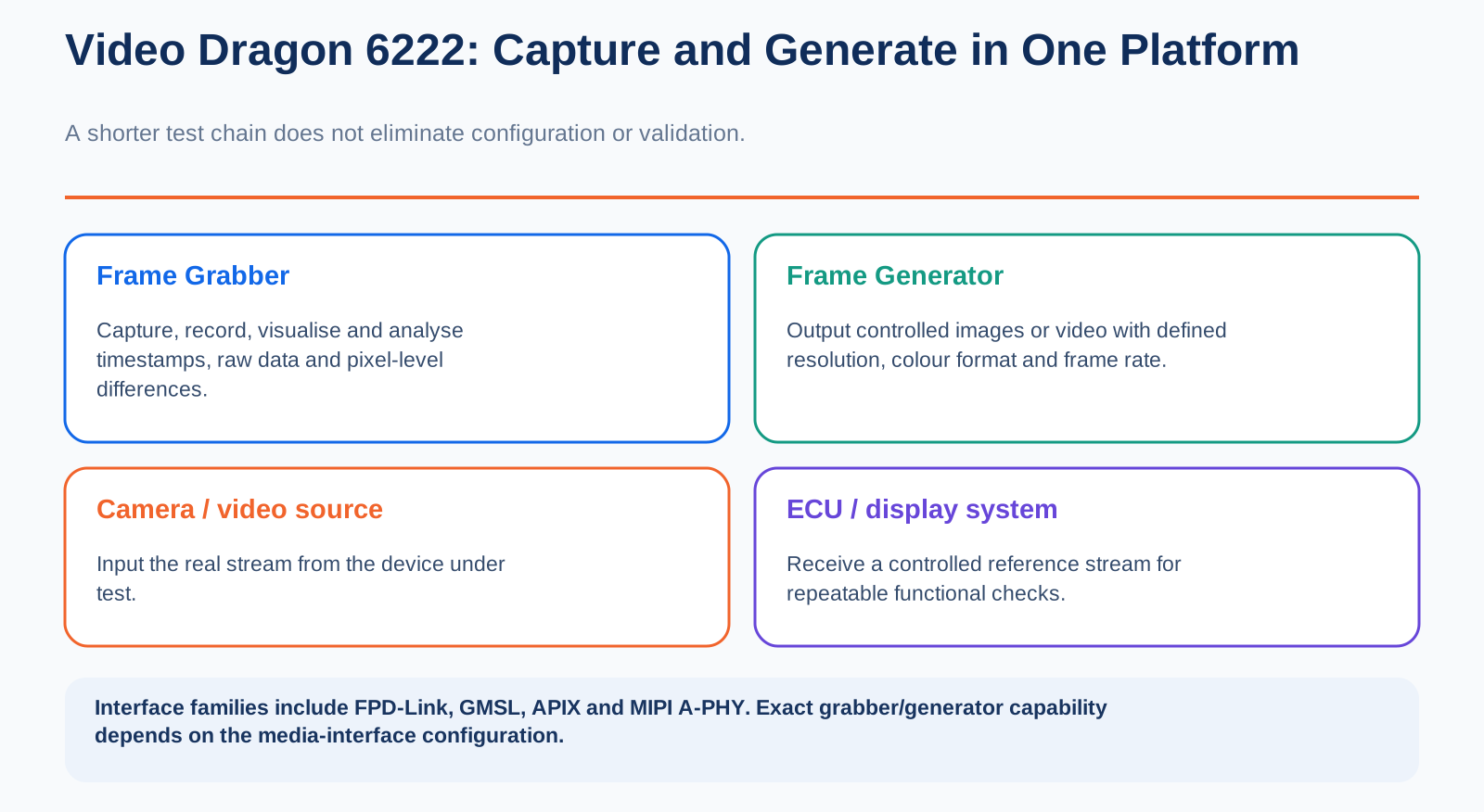
Its defining feature is the integration of a Frame Grabber and a Frame Generator in one platform: one side captures the real video output of a device, while the other supplies a controlled reference image.
Why does a camera test need both reception and generation?
1. A Normal Picture Is Not Enough to Pass a Production Unit
The traditional camera test is simple: power the device, connect it, watch the monitor, and confirm basic communications. For an older, low-resolution, low-speed product with a simple interface, this quickly catches a black screen, severe image corruption, or a failed connection.
A modern video link contains much more than a camera. The complete chain can include an image sensor, an ISP, a serializer, cable and connectors, a deserializer, an ECU or display unit, and sideband interfaces such as I²C, SPI, and UART for configuration and status exchange.
An image fault can originate anywhere in that chain. No camera output, a misconfigured serializer, poor connector contact, incorrect frame timing, or a display-decoding fault may all appear as a black screen. A visual check cannot isolate the cause.
Subtle faults are harder: pixel displacement, the wrong color format, intermittent dropped frames, incorrect frame order, timestamp drift, or a link that becomes unstable only after extended operation. These are difficult to detect by eye.
The production question is no longer simply “is there an image?” It is “does every frame match the frame the design is supposed to produce?”
2. The Grabber Finds Problems; the Generator Creates Controlled Test Conditions
A Frame Grabber can be understood as a high-speed video recorder. Connected to a camera or another video source, it records the complete stream along with timestamps and related metadata, and can compare images at pixel level.
Testing no longer depends on an operator staring at a monitor. The system can automatically check output images, frame order, and timing parameters, and capture faults that a basic inspection would miss.
A Frame Generator works in the opposite direction. It supplies controlled test images or video at configurable resolutions, color formats, and frame rates to an ECU or display device.
That makes it possible to remove the physical camera temporarily from the fault path. If the display still fails with a known-good generated image, the likely problem is on the deserializer, ECU, display-controller, or panel side. If the reference image is displayed correctly, troubleshooting can return to the camera and upstream signal chain. The search area becomes smaller much faster.
The grabber captures the device's real response; the generator provides a standardized stimulus. Integrating both creates the complete loop: output a test signal, capture the return, and decide automatically whether the result is correct.
3. Supporting Many Interfaces Does Not Make Configuration Automatic
Video Dragon 6222 uses a modular “common baseboard plus replaceable media-interface module” design. Depending on the selected hardware, it supports major video links including FPD-Link II/III/IV, GMSL 2/3, APIX 2/3, and MIPI A-PHY. Optional sideband communication can include UART, I²C, SPI, and MII.
The hardware is offered in three formats:
- G CAR 6222: a standalone unit suited to laboratory debugging and mobile field testing;
- G PCIe 6222: a PCIe card installed directly in a test computer;
- G PXIe 6222: a modular rack version for automated production systems.
Dragon Suite provides image viewing, video recording, test-pattern editing, and parameter configuration. The open G-API supports integration with automated test software, test benches, and HIL systems. Test cases created during development can be reused during validation and production instead of rebuilding every tool for each phase.
Modular does not mean that every function works as soon as a module is inserted. According to the supplier documentation, the chosen media-interface module determines whether a setup can capture video, generate video, or do both. Serializer and deserializer devices, coaxial or STP cables, adapter units, and sideband interfaces must all be selected for the product under test.
The host hardware may be reusable. Much of the continuing effort lies in interface modules, cable and adapter boards, and version control for the complete test program.
4. A Man-in-the-Middle Can Observe the Link, but It Cannot Replace Optical Testing
GÖPEL describes a typical Man-in-the-Middle operating mode. The tester is inserted into an existing video link and captures, decodes, or forwards the stream while the system continues to operate.
This is useful for diagnosing interface compatibility, timing faults, sideband-communication stability, and long-duration link reliability. Whether the inserted equipment is truly transparent still has to be verified in the actual program. Added connectors, cables, and test hardware can change signal loss, power conditions, or link-handshake behavior; a team should not assume that the system is unaffected.
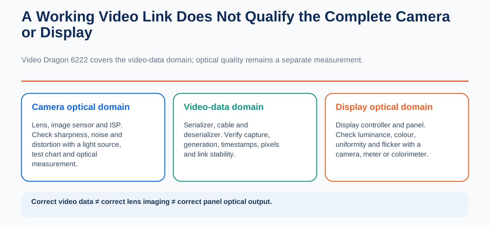
The capability boundary is equally important: Video Dragon 6222 operates at the video-data layer.
It can verify pixel data, frame information, timestamps, and interface communications. It cannot determine lens sharpness, optical distortion, inherent sensor noise, or color-reproduction quality. Those optical characteristics still require test charts, controlled illumination, and dedicated optical equipment.
The same distinction applies to displays. Correct video data at the display controller does not prove that the panel has correct luminance, uniform color, low flicker, or no defective pixels. Actual optical performance still requires measurements with a luminance meter, colorimeter, or camera.
A correct video stream, acceptable camera optics, and acceptable display performance are three separate qualification results.
5. A High-Resolution Camera Test Cannot Be Copied Directly from the Lab to the Line
During development, a team can record raw video for long periods, sweep resolutions, color formats, and frame rates, and repeatedly reproduce edge conditions. A production EOL station has a strict takt-time limit and cannot run an hours-long endurance test on every unit.
A more practical test strategy is layered from Stage 1 through Stage 4:
- Development: verify interface compatibility, image formats, and basic functions.
- Validation and endurance: record for extended periods to reproduce dropped frames, timestamp faults, and link-instability events.
- Production EOL: use short reference patterns to check critical pixel regions, frame timing, sideband communications, and device identity, while storing a complete traceable record.
- Sample-audit station: run longer and deeper tests without forcing every complex check into the fastest production station.
Public information confirms the hardware capabilities, interface range, and intended applications of Video Dragon 6222. It does not name specific automakers or industrial end customers, and does not document deployment across high-volume production lines. The platform should not yet be described as a universal standard for camera manufacturing.
Higher camera resolution increases more than pixel count. It also multiplies the data volume, interface states, and boundary conditions that production must verify.
Combining image capture and image generation closes the loop among stimulus, acquisition, and fault isolation. Whether the platform succeeds on a real line still depends on hardware-adaptation cost, automation integration, test coverage, and whether the required checks fit the production takt time.
Disclaimer: This article is based on public information for industry discussion only. It is not product-selection or procurement advice. Confirm equipment configuration, interface support, and actual test capability using current supplier documentation and program-level validation.