
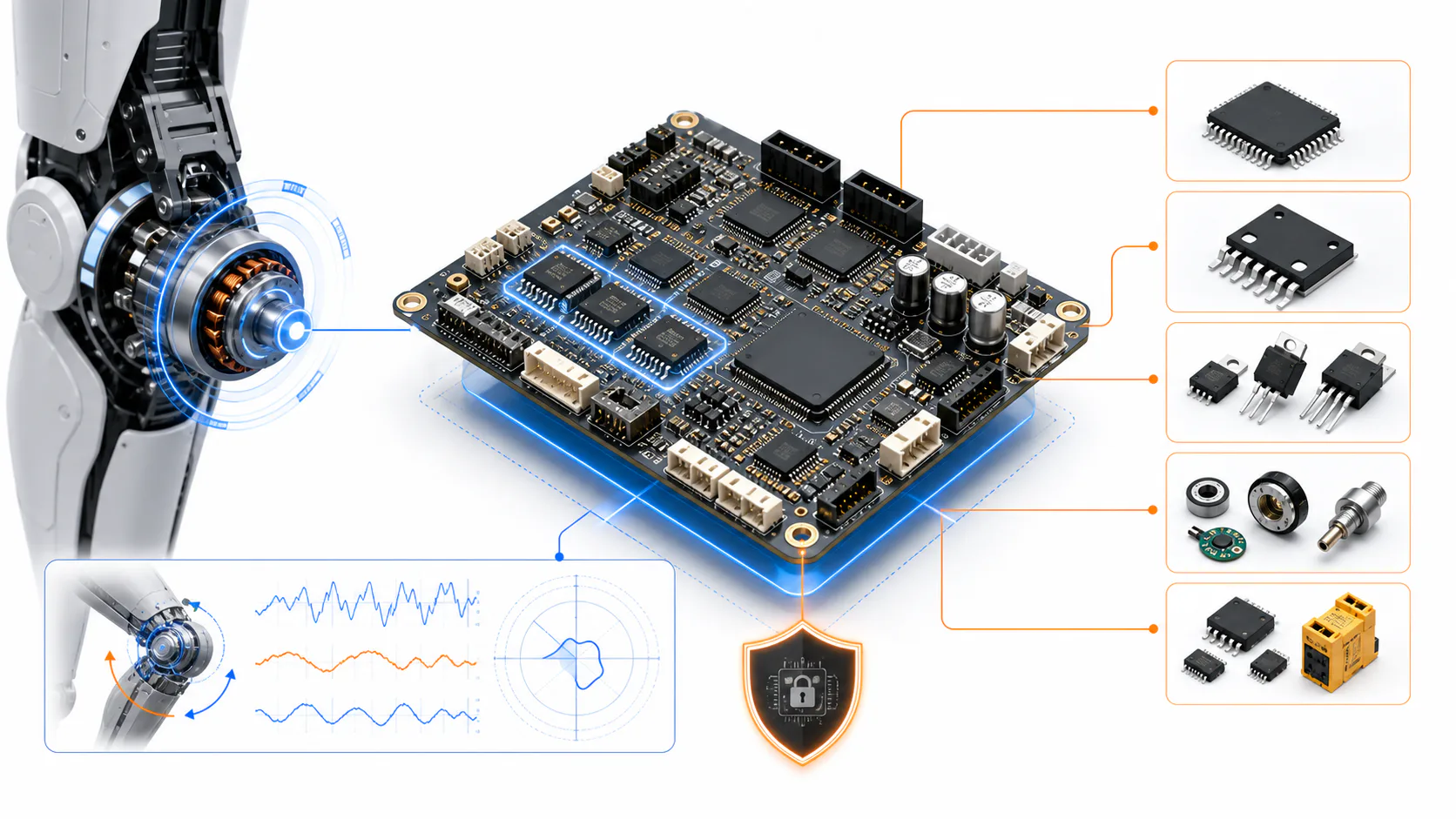
Texas Instruments updated the TIDA-010979 humanoid-robot joint reference design in March 2026. The reported 70 mm board combined a 48 V bus and 1 kW output with AM2612 control, three DRV7167A GaN half bridges, AMC0106M05 current sensing, EtherCAT, encoder feedback and shutdown functions.
The design was evidence of system integration, not evidence of mass-production adoption.
Device current is not joint current
DRV7167A device ratings describe a GaN power stage under specified conditions. Continuous motor current on a compact circular board depends on switching frequency, copper, airflow, mechanical conduction and the robot duty cycle.
Measure phase current and junction estimates through acceleration, holding and repeated motion. Include regeneration and fault energy. A peak headline cannot replace a thermal mission profile.
The 70 mm mechanical boundary makes layout and heat spreading part of the semiconductor decision.
Integration changes the qualification target
A joint drive combines real-time control, three power phases, current measurement, position feedback and deterministic communications. Timing, noise and protection interact.
An alternate GaN stage can change gate behavior, switching edges, EMI and thermal distribution. A different current sensor can change delay and fault thresholds. Replacing the controller can affect EtherCAT timing and safety logic.
Candidates should therefore be tested as a chain, not approved through isolated data-sheet comparisons.
A domestic option needs a reproducible stack
China-based GaN, sensing and control suppliers may offer candidate devices, but a list of local parts does not recreate a reference design. The engineering work includes models, layout rules, firmware, calibration, production test and known-failure behavior.
Procurement should ask which supplier owns cross-component debugging. If every vendor proves only its own device, the customer becomes the system integrator and absorbs the schedule risk.
Production evidence arrives after the demo
Robot volume manufacturing will expose batch variation, assembly yield, thermal-interface tolerance and field faults that a laboratory board cannot. Capture waveform limits, fault logs and calibration distributions during pilot builds.
Require traceability, PCN terms, failure-analysis response and capacity plans for each critical device. Preview or preproduction status must be visible in the launch schedule.
Maintain a controlled reference build with the exact PCB revision, firmware, motor, encoder and mechanical thermal path. Alternate evaluations should run the same torque, speed, holding and fault sequence and preserve raw waveforms. This makes a sourcing decision comparable across vendors and prevents a successful bench spin from being mistaken for joint-level equivalence.
The procurement conclusion
TIDA-010979 made the joint-drive challenge concrete: the valuable asset was a coordinated BOM and validation path inside a severe size and power envelope.
Buyers should qualify control, power, sensing, communication and protection together. A second-source program succeeds when the replacement stack reproduces system behavior and support, not when five individual parameter tables look competitive.
This article reflects reference-design information available through July 2026 and does not claim production deployment.