
A capacitor may have the right capacitance and voltage rating yet still fail a power board's height constraint. An enclosure or nearby heatsink can leave too little clearance, while moving the part may require rerouting the board. A thinner component can open up useful layout options.
Some specifications in Man Yue's MTL series reach a nominal thickness of 0.9 mm. Fitting the available height, however, is only the first check. Comparing MTL with Panasonic SP-Cap and KEMET's miniature polymer capacitors shows why height, footprint, capacitance and ripple-current capability cannot always be optimized together.
1. At the same 2 V and 220 μF, how much height is saved?
MTL belongs to the MLPC multilayer polymer solid aluminum electrolytic range under Man Yue's XLPC brand. It uses a resin-molded package with multilayer aluminum-foil anodes and a solid conductive polymer. Despite the flat outline, it remains an aluminum electrolytic capacitor, distinct from a multilayer ceramic capacitor, or MLCC.
For a comparable product, consider Panasonic's SP-Cap EEFSX0D221ER. It is rated 2 V, 220 μF, with nominal dimensions of 7.3 × 4.3 × 1.9 mm. Man Yue MTL includes a 2 V, 220 μF option with the same nominal 7.3 × 4.3 mm length and width, but 0.9 mm thickness. At the same capacitance, rated voltage and nominal plan dimensions, it offers more space above the component.
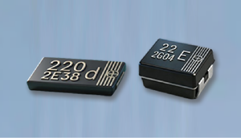
Figure 1. Product image from Man Yue's MTL material, illustrating the flat package form. It is not a photograph or scale reference for a particular complete part number.
This difference can matter when clearance directly above the capacitor is limited. If the overall product height is set by a connector or inductor, however, the benefit may be confined to local placement. First establish whether the thinner part resolves the board's actual constraint.
2. Thin is not the same as small: separate height from footprint
The MTL227M0DG09TRA0 is rated 2 V, 220 μF, with ±20% capacitance tolerance and nominal dimensions of 7.3 × 4.3 × 0.9 mm. The G09 package drawing specifies thickness as 0.9 ± 0.2 mm, so the capacitor body's upper thickness limit is 1.1 mm.
Allowing only 0.9 mm of clearance is therefore insufficient. Mechanical design also needs to account for solder height, PCB-to-enclosure positional tolerances and assembly margin. Although the MTL and Panasonic examples share nominal length and width, their terminal dimensions, tolerances and recommended land patterns must be checked separately before deciding whether an existing board can be retained.
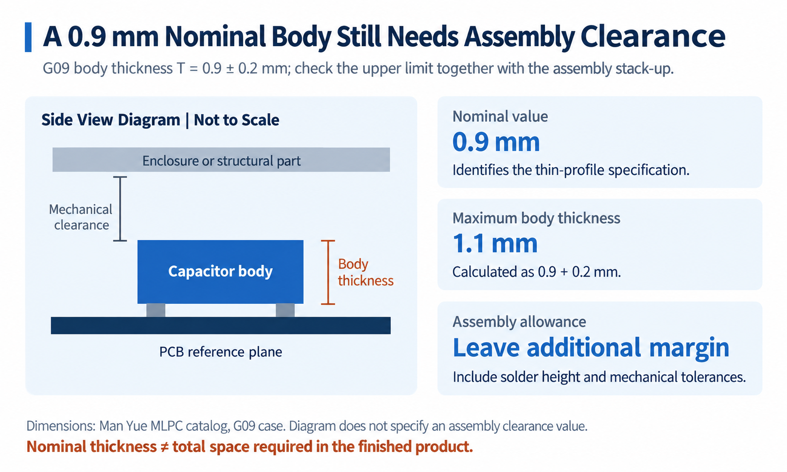
Figure 2. Assembly illustration based on Man Yue's G09 package dimensions. The 1.1 mm value is the maximum body thickness; it excludes solder height and complete-product assembly allowances.
Footprint remains a separate constraint. The nominal projected body area of this MTL is approximately 31.4 mm², excluding pads and surrounding clearance. If even that area is unavailable, other case sizes and material systems may need consideration.
KEMET's KO-CAP family uses polymer tantalum technology. Its T527 series emphasizes miniaturization and bottom terminations. The T527I107M006ATE100, for example, is rated 6.3 V, 100 μF, in an I-case 3216 package measuring 3.2 × 1.6 mm with 0.9 ± 0.1 mm height. Its nominal projected body area is approximately 5.1 mm². Unlike the aluminum MTL, it uses a tantalum anode.
The two products solve different space problems. MTL provides 220 μF in a larger body area. This T527 provides 100 μF and a 6.3 V rating in a smaller area. Combining multiple smaller capacitors to reach the required capacitance means recalculating pads, spacing and parallel electrical behavior. A smaller individual part does not necessarily make the complete solution smaller.
3. Equal capacitance and voltage do not guarantee equal ESR or ripple capability
Even after specifying “2 V, 220 μF, 0.9 mm MTL,” the complete part number matters. The catalog offers different ESR grades at the same capacitance and case size. Two MTL examples compared with Panasonic make the distinction clear:
| Part | Nominal thickness | Maximum ESR | Rated ripple current |
|---|---|---|---|
| Man Yue MTL227M0DG09TRA0 | 0.9 mm | 4.5 mΩ | 8.5 A RMS |
| Man Yue MTL227M0DG09TRX0 | 0.9 mm | 9 mΩ | 6.3 A RMS |
| Panasonic EEFSX0D221ER | 1.9 mm | 9 mΩ | 6.3 A RMS |
All three are 2 V, 220 μF. ESR is specified at 100 kHz and 20°C, and ripple current at 100 kHz and 45°C. Under those conditions, the MTL TRX0 option matches the Panasonic example's maximum ESR and ripple rating while offering a lower nominal height. TRA0 specifies lower maximum ESR and a higher ripple allowance.
A purchasing description limited to “220 μF, 2 V, ultra-thin solid polymer” therefore does not identify the required electrical grade.
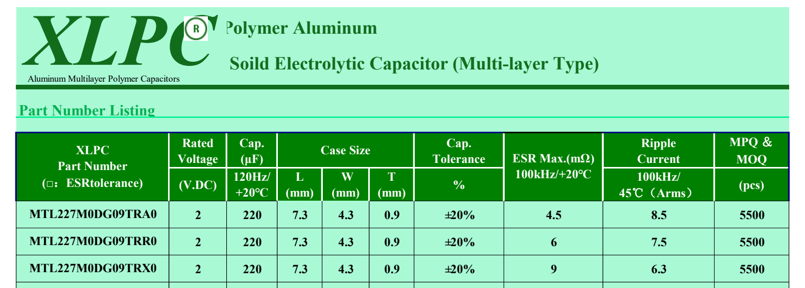
Figure 3. MTL specification excerpt from Man Yue's MLPC catalog. Complete part numbers distinguish different ESR and ripple-current grades.
Lower ESR reduces one component of loss at the same ripple current. During a sudden load change, output behavior also depends on capacitance, ESL and routing. TRX0 can first be compared with the Panasonic part using the stated parameters; TRA0 warrants further examination of temperature rise and ripple behavior. Final conclusions still require the same board and operating conditions.
The smaller KEMET T527 has a different electrical tradeoff: 100 mΩ maximum ESR at 100 kHz and 25°C, and 1 A RMS ripple at 100 kHz and 45°C. Its capacitance and single-device ripple allowance are lower than those in the table, and its ESR reference temperature differs. It is useful when considering a smaller footprint and higher voltage rating, but a high-ripple position requires renewed calculation. Similar height alone does not establish interchangeability.
4. The 8.5 A allowance falls as temperature rises
Ultra-thin capacitors often enter compact layouts, where cooling deserves equal attention. The MTL catalog gives these ripple-current temperature factors:
- T ≤ 45°C: 1.0, within the permitted operating-temperature range.
- 45°C < T ≤ 85°C: 0.7.
- 85°C < T ≤ 105°C: 0.25.
For the TRA0 example, the 8.5 A RMS rating at 100 kHz becomes 5.95 A RMS in the middle interval and 2.125 A RMS in the highest interval. Panasonic's SX catalog gives the same set of factors for these intervals. Compare both products at the same temperature; the 45°C rating cannot simply be carried into hotter operation.
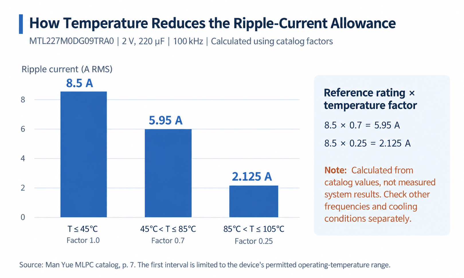
Figure 4. Ripple-current allowances calculated for MTL227M0DG09TRA0 using catalog temperature factors at 100 kHz. The intervals are shown separately.
Application restrictions also affect selection. Panasonic's SX specification dated May 29, 2026 explicitly excludes automotive use and continuously high-load applications such as accelerators and humanoid robots, pointing to other series for those uses. Similar electrical figures do not establish suitability for the same equipment.
The voltage rating must also fit the rail. The 2 V MTL discussed here cannot be used on a 3.3 V supply rail.
Man Yue likewise separates ultra-thin MTL from high-temperature MBL. For this MTL part, comparison should start with the actual low-voltage, height-limited location: verify dimensional tolerances and pads, determine the ripple allowance at operating temperature, then measure output ripple, load-transient response and temperature rise on the board. Panasonic's comparable specification helps frame the electrical comparison; KEMET's smaller case makes the footprint-versus-capacitance tradeoff more visible.
The value of 0.9 mm is realized only in the actual design. The saved height must resolve the assembly constraint, and the exact selected part must still satisfy ripple-current requirements at the real operating temperature.
Based on public manufacturer documentation checked as of September 17, 2026. Application suitability and substitution feasibility must follow the latest delivery specifications and complete-system validation.