
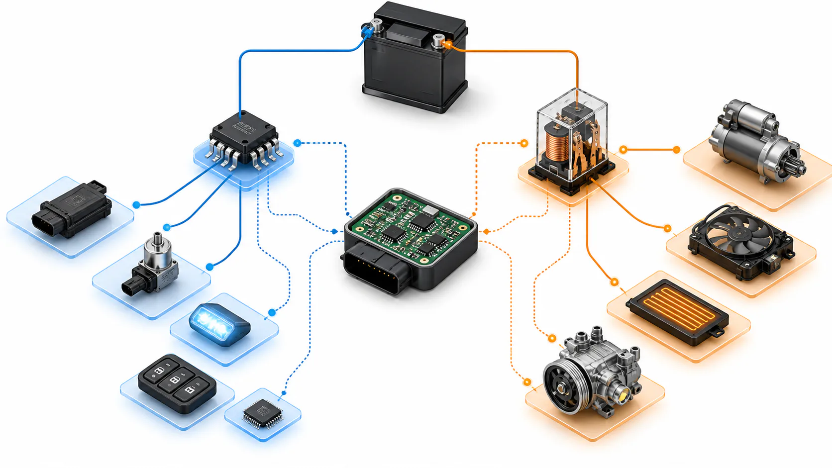
Automotive power distribution was moving in two directions in August 2026. Intelligent high-side switches were taking over more 12 V loads, yet high-voltage contactors were growing in voltage and current capability. The two trends were compatible because the devices solve different failure problems.
A sourcing team should divide the load map before comparing prices.
Smart switches win where diagnosis matters
Lighting, heaters, ECU supplies and smaller actuators benefit from electronic current limiting, thermal shutdown, open-load detection and software-controlled retry. A smart switch can reduce fuse and relay count while giving the controller information that an electromechanical device cannot.
Claims of one million short-circuit events, including those associated with selected NOVOSENSE and other automotive products, describe a defined test condition. They do not guarantee survival under every harness, temperature, battery and cooling condition.
The exact channel resistance, current limit and diagnostic interface still determine fit.
A relay rating is not a switch-IC rating
Continuous current, pulse current, inrush current and test current are different quantities. Package thermal resistance and copper area can turn an attractive silicon rating into a much lower board-level capability.
For products such as NSE34-family or SC77450CQ devices, obtain the original data sheet and test conditions. Confirm whether the published resistance is typical or maximum and how it changes with temperature.
Do not compare a headline current with a relay contact rating without a mission profile.
High voltage preserves the contactor role
Traction batteries require galvanic separation, controlled precharge and a defined open state after severe faults. Interrupting hundreds of amperes at high DC voltage creates arcing and stored-energy problems that a low-voltage high-side IC was never designed to manage.
Contactors therefore remain safety components in high-energy paths. Semiconductor solutions may assist monitoring and precharge, but replacing the physical disconnect changes the safety architecture and fault analysis.
Allocate each load deliberately
Create three groups: diagnostic low-voltage loads, electromechanical medium-current loads and high-voltage isolation paths. For every circuit, record normal current, inrush, inductive energy, short-circuit impedance, switching frequency and safe failure state.
Validate the electronic candidates on the real PCB with worst-case copper, ambient temperature and harness. Validate relays and contactors for arcing, welding detection, lifetime and coil control. Include connector and fuse behavior in both cases.
Keep the evidence by load and by software release so a later device or harness change can be requalified against the same fault envelope.
The procurement conclusion
Smart high-side switches did not fail to eliminate relays. They removed relays from the loads where diagnosis and resettable protection created system value, while contactors retained duties governed by energy and physical isolation.
Buyers should source against that boundary. The lowest-risk BOM uses each technology where its failure behavior is understood, rather than forcing one device class to win an entire vehicle.
This analysis reflects product information available in August 2026 and is not a current selection recommendation.