
What changes when a 48 V power board moves from current in the low tens of amperes to 35 A?
At 48 V × 35 A, the power path is already in the 1.68kW class. MOSFET conduction loss must be reduced; PCB traces or busbars must carry more current; connector temperature rise must be controlled; and even the common-mode choke at the power input becomes a difficult system-design problem.
More current normally requires a thicker conductor and therefore a larger component. More inductance tends to increase DC resistance and thermal pressure. A through-hole choke consumes board space and adds an assembly step. The development team wants smaller hardware, and manufacturing wants a fully automated reflow process, but the EMC test has only one concern: is the noise actually suppressed?
On July 23, 2026, TDK introduced the EP21 flat-wire SMD common-mode choke, ordering-code family B82552J*J021. The series is rated across 20.3A-35A and supports operating voltages of 48 V AC / 80 V DC.
EP21 points to a broader trend: high-current magnetic components are moving toward surface mounting and automated assembly.
1. Why Does a 35 A, 48 V Rail Make Common-Mode Choke Selection Harder?
A common-mode choke does not work like an ordinary power inductor.
It contains two coupled windings. During normal operation, current in the positive and negative conductors flows in opposite directions, so the magnetic flux largely cancels and the main current passes. Common-mode interference flows in the same direction through both conductors, so the flux adds and the choke presents high impedance to high-frequency common-mode noise.
The main circuit current does not create the full magnetic bias found in a conventional power inductor, but that high current still passes through the windings. As current increases, winding copper loss, terminal temperature rise, core size, and component weight all become major selection criteria.
EP21 combines MnZn ferrite with flat-wire windings. Four variants cover 160µH-640µH, and their rated current is defined at an ambient temperature of +70°C. If the enclosure temperature exceeds 70°C, the device must be derated according to the manual's curve.
2. Flat Wire Reduces DCR, but Low Resistance Is Not Zero Loss
The main advantage of a flat-wire winding in a high-current common-mode choke is a higher copper fill factor in the available window. Within a limited volume, the larger conductor cross-section reduces DC copper loss while supporting an SMD terminal structure suitable for reflow production.
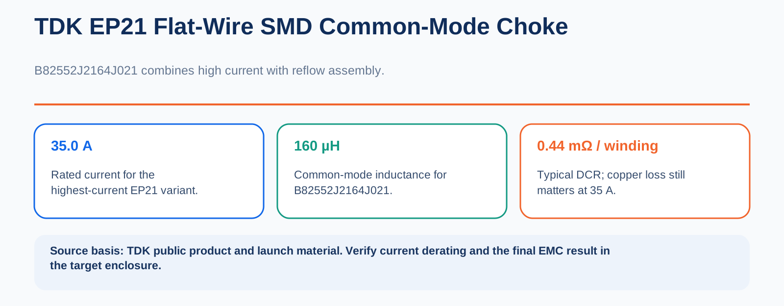
The highest-current EP21 variant, B82552J2164J021, is rated at 35.0 A with 160 μH inductance. Typical DC resistance is 0.44 mΩ per winding. At 20°C and 35 A, a rough estimate of DC copper loss across both windings is:
2 × 35² × 0.44 mΩ ≈ 1.08 W
This is only a static DC estimate. It excludes the resistance increase caused by temperature rise, AC loss, core loss, and the thermal conditions of the complete product. Even with resistance in the milliohm range, heat loss at 35 A remains significant.
The device uses bottom terminals and occupies 23.8 × 17.7 mm of PCB area. Its four-terminal structure improves mechanical reliability. For power equipment that aims to eliminate through-hole processing and use a common reflow line, that is more attractive than a traditional, bulky, through-hole wire-wound choke.
The flat-wire SMD architecture balances copper loss, PCB area, and assembly process. It does not make a high-current filter lossless.
3. None of the Four EP21 Variants Is Universal
The four ratings expose the basic tradeoff in a high-current common-mode choke:
- B82552J2164J021: 35.0 A, 160 μH
- B82552J2284J021: 30.8 A, 280 μH
- B82552J2444J021: 23.5 A, 440 μH
- B82552J2644J021: 20.3 A, 640 μH
As inductance increases, rated current decreases and DC resistance rises. An engineer cannot obtain maximum current, maximum inductance, and minimum resistance at the same time. Selection must begin with the system's limiting factor: insufficient current margin, or insufficient common-mode impedance in the target frequency range.
TDK data shows peak impedance for the EP21 variants in the 500 kHz–3 MHz region. The μH rating alone is not enough; the product's measured noise spectrum must be matched to the component's impedance curve. Switching frequency, harmonics, cable length, parasitic capacitance, grounding, and filter capacitors all affect the final EMC result.
Specified leakage inductance spans 200nH-900nH. Leakage inductance can attenuate some differential-mode noise, but it does not replace a dedicated differential-mode inductor or a complete EMI filter network. The correct sequence is to measure the noise, select the required impedance, and then verify current and thermal performance—not to choose the part simply because the table says 35 A.
4. SMD Does Not Mean Thin or Lightweight
The EP21 can create a misleading first impression: an SMD device with a compact footprint sounds small and light.
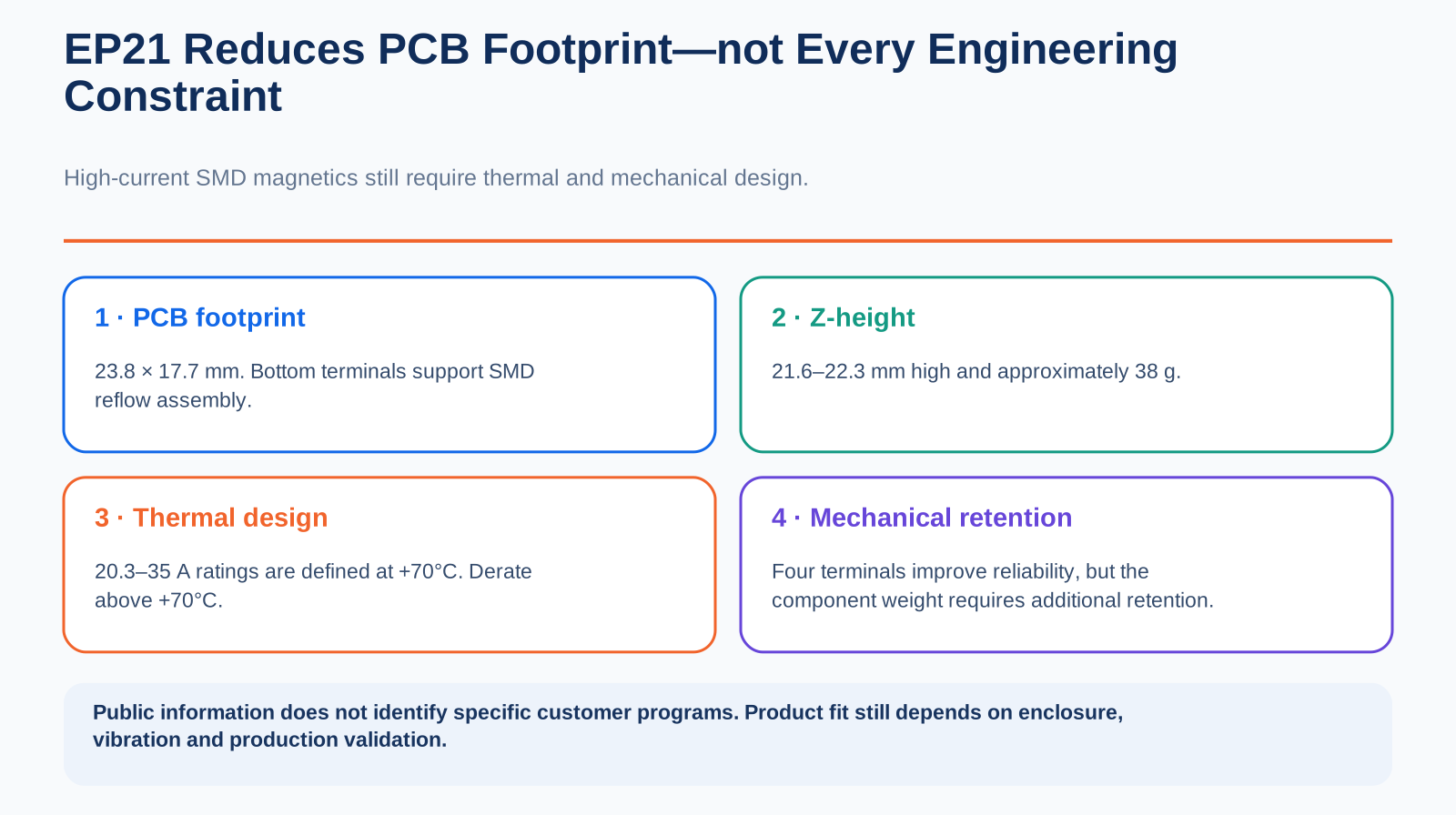
Although its PCB footprint is only 23.8 × 17.7 mm, the component is 21.6–22.3 mm high and weighs about 38g. It saves planar area but remains tall. It is not an automatic fit for a 1U power supply, a controller mounted close to its enclosure, or a high-vibration environment.
The manual explicitly warns that the component's weight is too high for the solder joints alone to carry the complete mechanical load. Additional mechanical retention is required.
Manufacturing must validate the reflow profile, solder-paste thickness, bottom-joint quality, and retention method. Mechanical design must also keep metal and magnetic parts away from the core and coil, because nearby material can reduce inductance.
EP21 optimizes PCB footprint. Height, weight, thermal derating, and mechanical reinforcement remain part of the engineering work.
Conclusion: The Question Is No Longer Only “Can It Filter?” but “Can It Be Built at Scale?”
EP21's value is not limited to its 35 A rating. It combines high current, low DCR, a small PCB footprint, and SMD assembly in one component platform.
Engineering and sourcing teams still need to confirm at least four points: whether common-mode impedance is sufficient in the target band; whether high-temperature current derating leaves adequate margin; whether the enclosure can accept a roughly 22 mm-tall component and its mechanical retention; and whether the complete product passes EMC testing.
TDK's catalog marks B82552J*J021 as a production series, but public information does not identify customers, end products, or shipment volume. The available evidence confirms the product specifications and supply status. It does not establish that EP21 is already a mainstream part in high-volume 48 V equipment BOMs.
Flat-wire surface mounting is not the end of common-mode choke development. It is the point at which high-power-density power systems push magnetics back into the center of system design.
Disclaimer: This article is based on public information for industry discussion only. It is not investment, procurement, or part-selection advice. Confirm specifications, supply, and qualification using the manufacturer's latest documentation and project-level testing.